Formula390

Supporting Vendor
Vendor
Country flag
Racers and street riders have been asking for a steering damper for the RC390, so it's time they got one! Introducing the Formula390 RC Steering Damper!

NO drilling of the triple tree or frame required! Initial prototyping for the mounting hardware is complete. We ended up having to abandon the idea of using a tubular style damper. Try as we might, it just will NOT fit! Even the shorty one we tried kept running into interference issues. So, we are going with the Scotts style damper!

The top bracket will mount to the top of the triple tree, and the bottom bracket will mount to the frame just in front of the battery box.

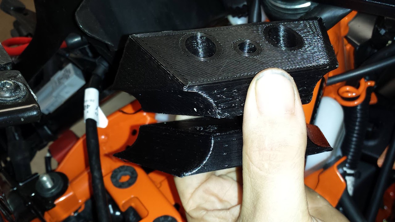
Initial prototyping was done in plastic with a 3D printer. Production models will be aluminum.

Here's what the frame mount brackets look like up close.
nNSNmYdFPJKUOVoxJytTqJTA5PTst6VQe5DYr-oaD8oOI35VPEux3l5ZJhbld-93tNmydr_Keom1SlAy7G-6mI_anFWiSv1IJ-jrGvxWNfR4taftGfOLWpl4aFIE9VhI7gzjK6MKdNOFnneLY2_NQsCdZ1PtJ87OJn8S72n0GIzvjfqvTfFCr-OT92Xe94a2Za-cDgtLgiZyn1144zKJguSjabnkzSuYOZAFIy6yvGlVd1Oq2SrI7SWK5QqiXyez-gDBPhyZQijjbrRxUbVWIK3mvTIuBQ4TuP6FcX85bWzDtTiUMSMv_28CCBAhG7dOz4KGvsq20K_gWcAKL1FtoVEIkPx12shlrtQOH1Epd1x4ASdYfUO3vq0Kgb62qYHX5phJCAYHUEIX7nFzf8vRoTPusdfbrX6Hs3hpCuseH3NmiTJdROiu0RwdjIp8jjdPmnzoxHuCFZ-SVasQKITEJSbxs_UIGAavWXEGNA2fvc3KkSKEIP4B63KVj-dsWOpJVzlCTetNq7K8cTwa6Y9kJ7Hdv2aQnetioHXIHP7vxGI=w1280-h720-no


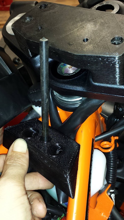
Showing the fitment with a dowel used in the pin mounting bolt hole to test and check where the pin meets in relation to the upper mount bracket.
za_lVUn3m65-UGazNd_m96Qj6Rcb4AZnzSx_ZNXOGsF33gGLHNDKNJWqEAEXDrKqio6Uf3kUFunv3ipN2eIZZ43hKNIT362w38GCjkTskQYbpsHCp7UHgQjMBYCD27Wr6PZX3CuyMt2NnqcDma-I32llN-WnYoaBpShKbX7MUHDoPDjalNxt2vVXWHxx9Elhremr8_C0DVmXJ8GmQRHzEn4gcTV81_atOvKZ5OfhI3HhL-dVf2ssX-YyXgqQKWn8GWpg9ir8_kvyhQ1-lk0hIQIFeXS_9-zzHmX9OMWHZg_b5mraEsJSugW0RTnQJz9WcE6qczmILDs6NpCHCEgrBc4giddknynljtB67oG8cZ1Auh9G0tdPu3cP6Slgpb5qyt344o2TVtUclnbH79EpUapoWxY_GHCQOAXamx_qAODirNbITaQINMXrspu6nECruUKDryyCA7chxD1VZdk6wngBHf3KfA45kx6eEz4nbkF-P0A7zWFFo28bCNoHpJtyakGUwQ0CezqIflzjzIryq7yo2sexeILrND7Ym3Ipntc=w506-h899-no


Closeup showing the frame bracket in relation to the battery box.
TFcPgc29lSXjR0TCVs_ydbmaVVCQuacBjBajHm6ACLlvuYJ6Eds9DPzv1GaAxAJEGtt-ixX7um3ylq325SHkk2MvjCLopP5d7smktwBD3Q9Ub8YnkF0Eo9r1iKYE0qHUSBt8SSVLmD1P2h6MkIWFTqbP8Hg-W-cimwKiqy-RtjmAVi1apz5QpfXM3_xK51stnkbV-TqqZpMbhC2Czw7CfeUagFKULSDfmACzMRhTp1DNfDCuQYyb-GFjplcL6BcPy7xuEgVFFF-iOIEF4KrzXPgT84tACAm5ovcHSSl3wV54eOX7_vqTuaC1O9VKEy5XPQoiaNvhWABxdGI-jbl6KYpDaX6qA0dITbTdnPyVBbalAcSufMPsc-gmws4icZeI1LJ0qIq7mRpVPbXkZGBd2n9d3ncMzDosjadOkp-TgT4ZdL54TJctwGLTSYxmfTMAbJkMAZ12ygNpmzU78HAFBeuVdbfRAVlaP_JUJC9X90V2oCIvQ5PdE2BD-G2wmjHKNGoKRmqaZXjIbGKCKA-YIo_TSEa7vD-il3PCUR8ZbNo=w608-h899-no


Testing fit with the battery box cover on.
YEyRLgp6UqBLKA--d3F3LoYDDTEz4EHYnIfKKOZllhad6HvCiWXPcoHmh6-dhgWnGpzyA2fGlVst2Piv-kOPYLmXWzVlAcsROKacVZETbAd2pQ6NSB6ykrqz2jZ0dkkXaQK_tnJ2ylDta5VBz2Dnfh09AA2UvBOmfoYWyq37HPCCv75HnxdocpPplNsUd2Lna_Xm2UmkH1G14IIb2NEMfiIuo9Lv76eo6p_Ebe84t1v6O3StQgLR_wvnftnmO4qejYR3PenMPkL-9ITEi3TCd831X02cy12q-S5t1rPiVJm0T1pUO5lJYtsTZz2nIDHtyp_ioZ3QPgXAH-kesQCSmQ3y0C1wiCgG3HaDdLfSGrXLboghZb1lAgBp0TqLNmwxOR7_0WVPT672SXktNLq9VujMgoqgFK7V6eJ_orlezJYphLZ7Womsp2jt9io38kT53vz56LvpOlAcKLJbfCjQNSQRYAxpI6AyE2Z6hLX1zr18C6IDdrNktyI_TXmglF-KNVVsSY_0UIsYjeHodgvZXpKTBLxlUFDGihjdF7fN4zU=w506-h899-no


As stated, these are the prototyped pieces created on the 3D printer. The final pieces will be made from aluminum, and the pin between the frame mount and the damper will be a solid 1/2 rod which is threaded and bolted to the frame mount upper piece from below with an 8mm cap screw. In the top of the rod, will be the steering damper pin which connects to the dampers control arm.

Note: Originally I'd intended to use a tubular style damper, but I just Could NOT get it to fit!!! Every method of mounting I'd tried ran into interference issues with the bodywork, fan, radiator, or fork tubes... so, that's when the design changed over to the Scotts type damper which mounts to the upper triple tree. I've tested fit with a 3D printed mock-up of the damper which was made to dimension from the published drawings. I have several styles on order, including a generic Chinese copy, a GPR V4, and a Scotts. The mounting hardware will be tested with all three, so folks can decide which style they want to use based on their preferences, and budget.

Production units should likely be available in about 2 weeks, maybe 3, depending on how trials go and how much work it takes to get everything aligned. There's plenty of room using this style of connection however (well, if one considers 1/2" or so "plenty" but us machinists target 0.001" for accuracy, so -I- consider that to be PLENTY of room! LOL
 

SPG

New Member
Hi Matt,
That looks very nice! One question though; the damper mount on the triple looks to be maybe higher and thicker than needed. Any chance to slim that area down a bit? Aside from weight, keeping things low reduces the likelyhood of damage in a crash.
Thanks for the excellent work so far!
-Sean
 

Formula390

Supporting Vendor
Vendor
Country flag
Hi Matt,
That looks very nice! One question though; the damper mount on the triple looks to be maybe higher and thicker than needed. Any chance to slim that area down a bit? Aside from weight, keeping things low reduces the likelyhood of damage in a crash.
Thanks for the excellent work so far!
-Sean

Oh, that upper bracket is by no means finished! As pictured it doesn't even show the cutout for the damper to fit into just that the mounting location was set in relation to the pin/frame bracket. That photo was taken more to show the connection pin attachment style, which was the part that took the most time and effort to develop, will be the trickest bit to fabricate, but was basically "feature complete" and ready for going into production... I'm really happy with how it turned out, and am very eager to get those first parts producted in aluminum to show to folks and make available for sale. If things go according to schedule (no plan survives contact with the enemy so we'll see) I should have the first parts in aluminum completed as early next week. Testing with the plastic parts off the 3D printer has worked great, but they wouldn't hold up for years. I may actually end up going with plastic injection for the frame clamps and top bracket, which is MUCH stronger than 3D printed parts, but I have to see how folks respond to the product offering first. Making injection mold dies is a considerable expense in time and materials after all... It would allow me to make a LOT of parts faster and potentially more affordable, but for that to work you need a certain economy of scale and enough sales to cover the costs of the molds.

The "plugs" that go under the top triple tree that fit into the two cutout holes are also not pictured... they were actually far easier to design in CAD than I had initially anticipated, and nailed 'em on my third try. There isn't much in the way of innovation or design there. It's just two plugs that fit in from the bottom, and would be drilled and tapped to accept the M8 bolts that go through the top bracket. Easy Peasy.

As for why these initial parts are plastic, I do a lot of prototyping on my desktop 3D printer. The iteration is fast and affordable, but it's also not without there being a certain amount of "home made" look sometimes and certain things in a print which are no problem with traditional machining operations are difficult to impossible to do with a home printer. One of the big things is any spans need support material, or you have to do other tricks... the upper bracket as pictured was just the quick and dirty "will this attachment style even work" basically. The bracket that had the cutout for the scotts damper I tested with looked UGLY because after I removed all the support material it looked like it had been badly chewn on by a beaver. LOL So I put one of the earlier prototypes for the upper bracket on just for the pin photos. It was more just to show progress in development than finished product. To make a bracket that spans the two cutouts on the triple was more the point I guess... and connecting to the plugs from below. Thus, no drilling or tapping required... I actually started redesigning the upper bracket in CAD the other evening (didn't do any work on it yesterday as I spnt the whole morning and afternoon fishing for catfish) but the current design goals for the upper bracket are to make it smaller, lighter, easier to manufacture and more stylist. That initial upper bracket was just the "can this attachment style even work" idea.

I'm into the refinement stage of the development now... The current design works great with my Scotts damper. I'm just waiting on the Chinese copy to arrive (should be very soon!) to make sure it works too so I can offer an alternative damper for those who might want a more "cost conscious" solution.

I'd considered attaching the damper to the triple via the steering stem / under the upper stem nut. My initial concern about going that route was I'm worried that it wouldn't have enough rigidity and if it did, it might then be so thick that the nut for the steering stem wouldn't have enough threads left to a solid thread engagement. To make it from sheetmetal, I would probably have to make it out of something like 14g (at least, maybe even 12g) steel. Then it's do you make it out of mild steel and paint/powdercoat, or go with stainless and offer it unfinished / polished or still go with powercoating. If needed due to cost considerations or feedback, can always put another prototype together with that attachment style I suppose. Making it from sheetmetal would involve notching the holes with my press, and bend it up on the finger brake, and see how it does. I just figured seeing as how I was already doing all that work on the lower brackets to avoid using sheetmetal, it made sense to make the parts the same way for the upper triple.

I suppose that's one of the disadvantages to designing in a vacuum. I go down a path that appeals to ME for MY aesthetics and MY manufacturing process and capabilities, then I go "OK, look at this. What do y'all think?" The chief problem with this sort of parts development is if I announce too early or ask too many questions, then it looks like I'm designing by committee, don't have any ideas of my own, or shows the design off before I'm either nearly in or after I'm in production... possibly letting the competition see what I'm doing. Then it's a race to production, followed soon after by copies of your part by others, and you are then in a race to the bottom dollar. {shrug} Look at the tail eliminator for example. We've got what, 4 different people offering effectively the same part. This is great for owners of the bike where they have lots of options... but it's difficult to put groceries on the table as the manufacturer. {double shrug}
 

Ryanthegreat1

New Member
Hey Matt,

Constructive criticism here I hope.

Have you looked at the possibility of mounting the torque arm for the damper below the triples? Then run a torque tube up the center of the steering stem to the damper on top? I know this would prevent the use of steering stem pin style front stand so that is a bit of a negative. On the plus side it would allow for the damper to be mounted much lower on the top triple clamp because you would not need to allow room for the torque arm. You could mount a torque tube to the damper and then drop it right down flush on the steering stem nut. Mount the torque arm after the damper is bolted down and done!

My biggest concern with your current design is the flex in the 1/2" rod used for the anchor point. That is a lot of stick out for even 1/2" rod. A piece of tube might be more rigid and I believe the GPR anchor points are hollow with a floating solid pin that mates to the torque arm.

I have a GPR on an XR650R and its anchor pin is a heavy wall ~13/16" tube about 3.5" long welded to a 3/8" plate to clamp around the upper steering bearing housing and anything above the first stiffness setting for damping you can see the anchor tube flex around.

All that to say I think the force for flex vs twist is significantly different. So if you could get the anchor point shorter for less leverage in a flexing motion you would have a stiffer mount.

I have this monkey.
GPR_stabi.jpg
 
Last edited:

waveriders

New Member
If you don't want to use the bracket to install a steering damper, that top mount looks like it would be perfect to mount a GoPro, lap timer, GPS, etc. :cool:
 

Edwardp33

Member
Country flag
I swung by the other day. Formula 390 is just down the street. The mount for the steering damper is gonna look really cool when finished. I am also hoping that Matt makes a similar amount for cameras.
 

Formula390

Supporting Vendor
Vendor
Country flag
I swung by the other day. Formula 390 is just down the street. The mount for the steering damper is gonna look really cool when finished. I am also hoping that Matt makes a similar amount for cameras.

It was good to put a face to ya' too Edward. :) The last of the tooling for production arrived today finally. So, tomorrow first thing in the AM, I will be starting the process of turning chunks of aluminum into the damper bracket for the first pre-production version of the damper hardware in metal. Once I've gotten all that finished, mounted on the bike, and test ridden it all... I'll be announcing the product availability with product shots et all. The alternative methods pictured here for mounting the damper to the triple are interesting. I may eventually end up with a v2 where I modify things, but for now, I'm not going to completely rework the design entirely to change for that. I think it's a very slick design (if I do say so myself) that I think y'all are going to love... both for the way it works, and looks, but also the price. Stay tuned for that... but I think everyone is going to be pretty happy! :)
 

Formula390

Supporting Vendor
Vendor
Country flag
Hey Matt,

Constructive criticism here I hope.

Have you looked at the possibility of mounting the torque arm for the damper below the triples? Then run a torque tube up the center of the steering stem to the damper on top? I know this would prevent the use of steering stem pin style front stand so that is a bit of a negative. On the plus side it would allow for the damper to be mounted much lower on the top triple clamp because you would not need to allow room for the torque arm. You could mount a torque tube to the damper and then drop it right down flush on the steering stem nut. Mount the torque arm after the damper is bolted down and done!

My biggest concern with your current design is the flex in the 1/2" rod used for the anchor point. That is a lot of stick out for even 1/2" rod. A piece of tube might be more rigid and I believe the GPR anchor points are hollow with a floating solid pin that mates to the torque arm.

I have a GPR on an XR650R and its anchor pin is a heavy wall ~13/16" tube about 3.5" long welded to a 3/8" plate to clamp around the upper steering bearing housing and anything above the first stiffness setting for damping you can see the anchor tube flex around.

All that to say I think the force for flex vs twist is significantly different. So if you could get the anchor point shorter for less leverage in a flexing motion you would have a stiffer mount.

I have this monkey.
View attachment 1420

Constructive criticism is always welcome. I live on it. You have some valid points, and I had considered them in the design.

The section modulus of a tube is the section modulus of the OD (as if it were a rod) minus the section modulus of the hole (as if it were a pin removed). A pin is stiffer but... has a lower stiffness to weight ratio (section modulus goes up with r^4, weight with r^2) so a tube is stiffer than a rod of the same weight but less stiff than a rod of the same OD. In some cases like bending loads or cantilevers there is less deflection (stiffer) with a tube when the weight of the rod itself is a consideration - getting rid of the lazy material at the center (remember that r^4) makes it deflect less under gravity or other loads. Hence I-beams, the hard working metal at the extreme fiber is kept while the lazy material toward the center is discarded.

The "extra" material of the solid pin, won't contribute significantly to the weight. So by MY reading of my mechanical engineering (and consulting with two professional Mechanical Engineers) the indication of going with the solid pin should be fine. It worked quite well even when I was using the plastic 3D printed parts for the frame mount and triple brackets. I had large fender washers sandwiching the plastic parts, just so I didn't obliterate them in the road testing, but everything worked much better than I had anticipated the plastic printed parts to... I was basically using them just for fitment, and decided to try to see how it did all bolted up. It worked! Obviously they wouldn't work long term, so I'm still fabricating out of aluminum for the final parts, but it tested things enough to prove out the design. It's a valid concern you have to be sure... but I think it's going to work out quite well and if the GPR pin is flexing that much, I know my design is more ridged than that even with the plastic parts. I'd considered going up to a larger OD on the pin if necessary, but so far at least, things seem to be OK. If it goes much larger, then you'd have to pull the frame clamp hardware off to remove the battery box lid... something I worked quite hard on trying to get the design done such that one COULD still remove the lid without having to pull any of the damper hardware off... something that is NOT the case with the GPR unit. To remove the battery box lid, if you have the GPR unit, you have to pull the damper and frame clamp. My design, it's a little bit of a "one side then the other" song and dance, but I'm AM able to get the lid off and back on again. It's not the easiest thing in the world, but after I did it about 5 times, I'd figured out the trick and was then able to do it much faster. Not that we are getting in there all that often, but it's nice if one doesn't have to reach for a wrench to gain access to the battery box!
 

Formula390

Supporting Vendor
Vendor
Country flag
MUCH progress was made today on the damper mount kit.


The 5 main components of the brackets (top and bottom frame clamp, triple mount, and the two triple plugs) are all machined! I made one minor mistake while machining, which really was a non-issue, just an aesthetics nitpick on my part. I did some math wrong and machined the cap screw recesses for the top frame clamp slightly too deep, but it's a non-issue functionality wise and this was preproduction testing the manufacturing process so, ok... Issue found and will be resolved when I go into full production next week. The production units will have the cap screw had recessed like the top triple clamp mount bolts, where the top of the cap screw is recessed such that the top of the cap lands at 1mm below the surface.


There were a few spots of porosity in the casting which turned up during machining. I didn't flux the pour, so that wasn't surprising. I also had a small shrink on the top triple damper mount as well... which for the purpose of testing I just filled that area with bondo. So I will need to adjust how I do the gating and risers for the production castings, and obviously flux the melt prior to doing the pour. That will remove the rest of an my impurities in the metal that hasn't been skimmed off already as dross, and degas the melt to prevent any porosity. Otherwise, the castings pretty much worked out just great. They mold up great, the patterns are able to be extracted cleanly, and other than adding a little bit to them for machining ease they are good to go for production. Plus, I managed to not scrap any parts today! That's always a good day for a machinist! LOL


Once all the machining was completed, deburred, wiped and hit with an air hose... it was time to test the fitment with the metal parts! The moment of truth! 4 weeks of planning. Everything bolted up, aligned, and no fitment issues, none! It all lines up and fits, just as prototyped with the plastic parts. Whew!!! :)

Tomorrow at 9am we will start the lathe work, which should go pretty quick. Then it's pull it all off for paint, road testing, product photography shots, and announce the product as available for sale!!! So. Fscking. Close.
rIjb_DeFFOLKHk2n3yCKF_AGjTsCv4Uv0bwGwcEqRI_V3W6ZCXXvy01prBEDuLxPyLVT16FakM1LiTSqCaq7cea9TPtJO8vv0EvDQV3laE47Kh8gV4HlvTeS0VHYtJzbgrZ9ZsQP8ZLVijVPkZ_crUI1zUGfKuk86t8f5Fb17XsSvHRhNlivYIaTR76hAy9uG93Mg6HhPnLfrTguoxmzqz2dO9ZtG53NFGMZM47_teXjjobp2-annwDoG_wy7kkSYcg0i0bBFECWHcz2v9C7hcFf9uTSejXuOOoep0LvBKuG59Jk7RVp2M9MmuxntaHVlhVRWiUT3Y1JyBGzWvB3f0hV0vvAkff-QAnQNhRudjCkGhBes9JRDE7G8936rNLHHN3nx-xwSTX9CQTnW9UNDKKGW6XtucpkKtpmVkajISgF1JurQFdk0OJdXpB4Jhny6Jt9qk_ufEc2xjrQ9Nj3KhTRhZiOF8pqtSY-SFLwVaGVpMzWGPbcrgUrCGpFFjRQ4Ua_8TM0u4USamFqCeuBhxlld8D5Ks3LPelntaLSbIF0=w1080-h1440-no
 
Last edited:

Formula390

Supporting Vendor
Vendor
Country flag
Todays progress on development

So here is todays progress on the development for the damper kit:
damper-3.jpg
damper-7.jpg


Based on the feedback from Ryanthegreat1 I increased the pin diameter from the 1/2 I'd initially planned on using, to 5/8" (0.625")... well, everything fit, all was perfect. Then I tried to put the battery box lid on... {sigh} The increase in diameter meant that the pin location and extra material is now making the lid install and removal too difficult to do. At 1/2" it was working. It was a little bit of a back and forth, but it worked. Well, at 5/8", nope. Plus, the extra space I had between the box lid and the pin is now gone so the lid now nearly contacts the pin. So, I'm going to have to decide on if I want to either go to the 1/2" pin (which didn't flex with my prior testing, but I see the reason folks are concerned) or keep the 5/8" pin, and re-work the top frame clamp to move the pin such that the larger size doesn't interfere with the lid removal or install. That's R&D, so I anticipated the change in diameter being a potential issue. Just all the points that I expected it to cause problems were fine... so I thought I was in the clear earlier in the day. Shoulda knocked on wood at some point of the morning I guess! LOL Now, the GPR damper DOES require removal of the damper and arm, to get the lid on/off... so this might be much ado on my part about what might just be "The Way It's Gonna Be" but I'm going to TRY to get it such that folks don't have to reach for the toolkit to get the lid on/off. If I can't make that happen, well... that may just be the way it goes. I'll toss a few more days of development at it tho, and see if I can resolve the issue.

damper-11.jpg


I also ran into a slight issue where the frame clamp slid backwards on the frame after it was clamped. This surprised me, because I didn't have this issue with the design with the plastic 3D printed parts. I had added some gasket material between the aluminum frame clamp and the frame, to try and protect the paint/finish of the frame. The LAST thing I want is somebody making a big ol' stink because "OMGWTFBBQ!!! The frame clamp made a mark on my powder coated frame!!!!" 'cause ya' know... who'd ever expect clamping metal to metal to do something like that. You know, other than anybody who's got a clue... but anyway! So I tried both paper gasket and rubber gasket. The rubber was a waste of time. One, it was thick so it moved my pin location... not much, but enough that I wasn't too happy already. I've spent a LOT of time trying to get that pin Dead Fscking Center!!!! on the torque arm of the damper... and then it moved a tiny bit with the damper set on it's highest setting.... which caused it to loosen just enough that I thought I was seeing flex in the pin. Nope... the whole works slid back and THAT was the issue. OK, so I then moved to heavy paper gasket material. That held a LOT better. It held REALLY well... but after riding 25 more test miles... sure enough... it moved the tiniest of amounts. It wasn't loose, yet, but I fully expect that it would continue to loosen eventually and would require tightening. So, I'm having to think about how to try and protect the frame from the frame clamp. With metal on metal, it stayed put just fine even at the highest setting and showed no signs of any flex in the pin... but I also noticed sure enough... a tiny mark on my frame from the clamp contact. While -=I=- don't care the least bit about that, I know somebody out there will, so I'm going to TRY to do something about that. That said, I will NOT tolerate some protection method that causes the frame mount to move and loosen, nor do I expect ya'll would either... but I ALSO don't wanna get an email from some wanker pissed off there's now a nick on their paint. {shrug} The metal on metal as well as the plastic on metal parts all stayed put... but I also hadn't put any sort of gasket type material in there yet either... {shrug}

I'm sure I'll figure something out, and I can continue to mull the whole "how do I protect the frame from the frame clamp" issue while I work through the pin diameter clearance issue. That will take a few days to get a new design drafted in CAD, print the updated design on the 3D Printer, test the fitment of the newly printed parts, then once I'm happy with relocated pin... start anew with the fabrication and machining of the updated part in metal to test IT'S fitment and clearance...

So, I was hoping to start production first thing Monday, and be announcing product availability for pre-production sales this evening. No Plan Survives Contact With The Enemy... or in this case, incorporating feedback from the community... specifically... that damned troublemaker Ryan!!! ;) LOL
 
Last edited:

Formula390

Supporting Vendor
Vendor
Country flag
Ok! The frame clamp revisions are done and tested with the 3D Printer parts. Tomorrow morning I'll print the revised casting patterns, cast the two updated frame clamp parts, machine them, and give everything another road test. The larger diameter pin has been retained even! It took a few iterations (six in fact) to get everything JUST the way I liked it, but it's looking great. It's a little bit trickier to get the battery box lid off and on without having to loosen or remove any of the parts of the damper kit, but it IS still possible! That was a big goal of mine as I didn't want the need for tools on the road that might not be in someone's toolkit. The only tools necessary would be a 5mm (for the M6 cap screws on the damper and triple clamp mounts) and 6mm (for the Frame clamps and torque arm pin) Allen keys... Plus, the revised frame clamp no longer requires unbolting the battery box to get the lower frame clamp in place. So I'm pretty pleased with spending the extra time on the design, was able to incorporate the forum feedback, and looks like I'll be in full production likely by Wednesday, or possibly Thursday! :)
IMG_20151004_203915.jpg
 
Last edited:

Bagwell

Member
Country flag
I may have missed your mention of it, but does the damper have to come off and rod out to remove battery box cover?
 

Formula390

Supporting Vendor
Vendor
Country flag
I may have missed your mention of it, but does the damper have to come off and rod out to remove battery box cover?

The battery box cover CAN be removed without having to touch the damper hardware or mounting brackets. It's tricky I'll be honest, but it can be done. It was easier with the 1/2" pin, but it'll still be possible to remove. You have to do one side then fasten (or unlock) the latch, then do the other side. The front of the battery box lid contacts the pin while getting the second side over the edge of the battery box to fasten the lid to three boxes tab. It was easier with the 1/2" pin because you had a tiny bit more room... As I'm sure you're aware . Even without ANYTHING between the battery box lid and the steering head things were a bit tight... It's very easy if you just loosen the frame clamp enough to rock the pin forward... But that requires a 6mm Allan key, something one might not have on the road... That's why I was trying to be sure it's at least POSSIBLE to remove the lid without tools. With all that said, putting a 6mm Allan key in the bikes toolkit would likely be the easier thing to do. It's worth noting the GPR damper requires removal of the damper and the pin to get the lid off. I'd likely have preferred to have kept the 1/2" pin as I'd originally designed and planned on using, but the feedback was a desire for as stout a pin as possible, so, I made it larger and modified the design to accept it. If someone wants the 1/2" pin, it's TRIVIAL to turn that on the lathe while I'm making the parts. Currently I'm using 1" stock (already had enough on hand) but the current plan is to use 3/4" stock to turn down to 5/8", so it's just a few more roughing passes to continue turning it down to 1/2" if that's what a customer desires... :)
 

SPG

New Member
Hi Matt,
At the risk of bringing up things you thought about weeks ago... How about milling a small flat half way up the pin, or if the pin needs to rotate, you could step it so that it is 5/8 at the base and 1/2 at the top half. You would retain most of the rigidity, and still have the clearance.

Second, if the frame clamp was made a little wider, the contact with the frame could be a V shaped groove. This would self align and not move fore and aft with use.

Looking forward to production. Please put me down for one from your first batch, you are saving me the trouble of milling one :)
-Sean
 

Formula390

Supporting Vendor
Vendor
Country flag
Hi Matt,
At the risk of bringing up things you thought about weeks ago... How about milling a small flat half way up the pin, or if the pin needs to rotate, you could step it so that it is 5/8 at the base and 1/2 at the top half. You would retain most of the rigidity, and still have the clearance.

Second, if the frame clamp was made a little wider, the contact with the frame could be a V shaped groove. This would self align and not move fore and aft with use.

Looking forward to production. Please put me down for one from your first batch, you are saving me the trouble of milling one :)
-Sean

I'll likely add a flat to make tightening the pin a little easier. For my testing I've just held it with a pair of pliers with a shop rag to protect the finish, but a flat to allow a wrench might make things a little easier. It's two additional operations, but that's not TOO terrible. For a step, I've got it sorted enough I think that the larger diameter pin as requested seems a reasonable enough request. Fact is, sometimes the way a part LOOKS is just as important as how it performs... and so if a 1/2" solid pin looks like it would have flex, it may be perceived to... even tho all the math in the world (and my testing) show otherwise. {shrug} I think a major issue is folks are comparing it against a thick wall tube, and with such a short length pin even the small diameter pin is MASSIVELY rigid compared to the resistance of the torque arm... I think being concerned about flex of the pin is a bit over stated anyway. So what if the pin flexed a little? Really... I mean, that just becomes part of a low speed damping circuit basically. LOL But, whatever. :) :)

For the frame clamp, the width is such that it wraps around the far side of the frame so that as you tighten, it pulls the clamp forward. I've added a "bumper" onto the front, to provide a max distance it can travel forward. This is 3/8" wide, so if necessary (because of a fugly weld perhaps) the customer could grind this bumper back to allow for fine adjustment alignment of the pin to the torque arm. The camp "finds it's happy place" this way, and yeah... doesn't move fore or aft, and doesn't require massive torque down to stay in place. Plus, you can find adjust the position if necessary this way with adding spacer / gasket material between the frame and the clamp, which also allows for a bit of fine adjustment of position and allows for tolerance in the Bajaja manufacturing of the frame. :)

The new frame clamp parts are cast, but my back is screaming at me, and I skipped breakfast and lunch... so I'm calling it a day. I'm gonna make some dinner, pet the pooches, and watch some cartoons while the 3D Printer cranks out copies of the pattern for the 3 triple clamp mount pieces. I figure I can make about 4-6 of the main triple mount per pour, and 8 or 10 of the plugs minimum... so, gotta make a BUNCH of patterns to be able to quickly and easily do all that. I'll make up a molding board to fit my flasks, and should be a good process for production. For the frame clamp pieces, I'll have those updates finalized tomorrow I'm sure. Just TOO MANY years of testing won't allow me to declare I'm "In Production!!!" without final testing the whole chain from pattern to casting to machining to mounted to road tested... without doing the full process, cradle to grave, as it were. I tested the plastic parts tho, and they worked GREAT so I have no reason to believe the metal parts won't do similarly.

Here's what todays castings look like:
IMG_20151005_151639.jpg

They will be sawn apart, ground, and then machined, starting tomorrow morning. I was hoping to have them machined today, but I'm gonna wuss out and cry "Give me a few extra hours... I'm an Old Man here!!!" Heh.

The patterns next to the just cast parts, not even pulled from the sand yet:
IMG_20151005_150948.jpg

Just a quick look at the flask, with the riser, sprue, runner, and gates cut... just before I buttoned the flask up for the pour.
IMG_20151005_142633.jpg

They turned out great. The detail even picked up a bunch of the 3D printed layer lines that sanded nearly perfectly smooth to the touch (I got tired of sanding to be honest and just wanted to do the casting already!!! LOL) but were still there visually. You can hardly feel them if at all with your fingernail... and there they are in the cast metal! I'll be honest... some days I just love my foundry man!!! :)

Depending on how quickly I can manage to get all the pattern pieces printed, sanded, sealed, and mounted to the molding board... will determine which day I ACTUALLY start production, but it'll likely be Wednesday, maybe Thursday at the latest. A buddy of mine wants to go fishing for catfish again... so I might have to declare a mental health day... and go see which is smarter... me, a fish, or bait stealing son of a ***** turtles. I'm laying odds on the turtles myself.
 
Last edited:

SPG

New Member
Thanks for the reply Matt. Just to be clear, while a flat would certainly make for ease of tightening, I was thinking it would add a little clearance for removing the battery cover while maintaining the increased material on the bottom half of the pin for rigidity.

Nice work. Have fun fishing!

-Sean
 

Formula390

Supporting Vendor
Vendor
Country flag
Thanks for the reply Matt. Just to be clear, while a flat would certainly make for ease of tightening, I was thinking it would add a little clearance for removing the battery cover while maintaining the increased material on the bottom half of the pin for rigidity.

Nice work. Have fun fishing!

-Sean

Ahhh! Duh! OK now I see what you were saying. Yeah... that might work. I'll have to consider that. I am also considering instead of making the top of the pin where it intersects with the torque arm to have flats on the side of it, so I could have a LITTLE more rigidity at the top of it too. It would be pretty quick to turn the whole thing at 5/8" diameter, then turn a step down to 1/2" near where the battery box lid would intersect, and then turn the final step down to the pin end 6.2mm stub that goes through the torque arm. Oh actually! If I'm turning flats, I wouldn't even need to step down to 1/2"!!! The flats can do that... -=AND=- the lateral dimension would remain the same as the 5/8", so the dimensional rigidity would remain the same! Hey, hot damn... that might just give the best of both worlds! My thought was to turn the very end down to say 8mm, the turn flats on the sides, 180 out using a 5C collet square block and support the other end with a machinist jack. That alone would most likely be rigid enough without having to put a hold down on the part against the jack... tho I suppose I COULD always just use a quick toggle for production. It's not like I'd be taking heavy hog cuts on it anyway... going from 5/8" to 1/8" could really just be a few passes at 0.030" and final at 0.005" and done. It is, after all, just aluminum... and this isn't exactly hogging material out anyway. Hmmm. I could use that same setup to also do the flats for the 1/2" at the same time, just 90 out from the flats on the tip. Hmmmmm. It would just be changing the height of the knee, and it's quick enough to spot against the part with the knee using some 0.001" tho rolling paper to still get the accuracy I'm after, but quickly for production... and without having to spend a ton of time on setting up each different operation too! That WOULD give some extra clearance, and not REALLY add much machining time. Yeah, it's two extra operations... but if I'm ALREADY setting up with the collet block, it's simple enough to do. Hmmmmmmmm. I'll just have to see. I've already got 7 more operations in the machining than I had initially thought I was going to have when I did the initial setup with the changes to the frame clamp. When it's being done on the prototype tho, that's a bigger deal because each setup (as you know) takes 20-40 minutes, when the actual operation might only take 5-10 minutes. So the "per piece" time for the pre-production unit takes a LOT of time for each piece, because of all the setup... but once I'm in production... then it's say 40 minutes of setup, then just 5, 5, 5, 5, 5, 5, 5 as you roll through each piece, assembly line style... so the setup time almost becomes inconsequential when averages across all the pieces being machined. Plus once I've got the setup for the collet block, spinnng the block and running the operation isn't all that much. That may work, address the concerns I have with increasing the overall pin diameter, and give a flat to put a wrench on for tightening still. LOL I think I might have just allowed you to talk me into it here! Heh! I'll have to take a look at it once I've gotten it all on the machine. I may lathe out another pin today (just have to see how much time it takes to machine the two frame clamps today) and use that for the road testing. Worst case I might just machine the existing pin... but I HATE have to re-center work I've already turned on the lathe plus I'd rather not risk putting marks on the existing pin with the chuck. Yeah, I can add some paper or aluminum can spacer between the park and the jaws of the chuck... and I technically COULD just toss it in the 3 jaw and the center will be "close enough to close enough" without having to go through the full blown center to 1/2 thou with the 4 jaw... but the machinist in me just recoils at re-chucking a previously turned piece in a 3 jaw "just to save a little setup time!"... as I'm sure it does you too. LOL
 
Last edited:

Formula390

Supporting Vendor
Vendor
Country flag
...and with this latest revision to the frame mount... I can now declare:
THE STEERING DAMPER KIT IS NOW OFFICIALLY IN PRODUCTION!!!
IMG_20151006_141144.jpg

I'll test the change to the pin as discussed earlier, but that's a totally zero risk change. I'm also still researching between anodization vs powder coating. I'm strongly leaning towards powder coating tho as the gal that does my powder coating in town is FABULOUS, and KTM Orange should be a possible option... :)

I just got back from the test ride and it's terrific! The spot where I was consistently able to get headshake... Gone!
 
Top