DIY O2/Lambda Eliminator

mr-fabricator

New Member
Count me in for one buddy , i tried the resistor type a few weeks ago , obviously an epic fail .

With regards to throttle and starter button , im running a cheep domino throttle bought from a uk ebay store , 25aud ish ( bought 2 so have a spare ) slight mod to original cable and it works a treat . Start button was 4 bucks again a chinese ebay purchase . Kill switch is on left handle bar and i used a N/C micro switch and when pressed it breaks the coil live . Also doubles as a thumb operated quick shifter but to be fair im quicker rolling off the throttle .

Keep all of your good work up boys ....

Regards lee
 

cjwell

Supporting Vendor
Vendor
Country flag
@cjwell What is the KTM "Cup Switch" and throttle?


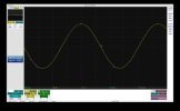
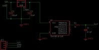
FYI: I just prototyped a circuit to simulate a narrow band O2 sensor which simulates the oscillation of the closed loop circuit (not a straight resistor hack that doesn't work for this bike). It all checks out on the 'scope but now I just need a bike to try it on! I have a very small run of PCB boards being made (should have them in another week) and can make more and sell as a kit (around $20-25) or it's all open source if anyone wants to copy it and build there own (I'll post a GitHub and OSHPark link when its closer to being done). This would only initially be for the hardcore tweakers who really want to dive into the gory details of ECU hacking. For most non-tweakers you should just wait and get the Power Commander when it comes out and go ride the shit out of it and not worry about these things. :)


On the cup conversion fiche, there is a throttle and right hand switch. The throttle is an rc8 one, the switch is probably a modified harness end one off an rc8/rc8rs. The stock throttle and switch are in same housing. "I'm" guessing/hoping the switch is set up to bypass key ignition switch like they did on rc8rs model. So for track bikes you can get rid of key switch and have separate throttle. I will know more when they arrive... I have on order. Since they are made together stock, to change the switch you need stand alone throttle housing.
 

micahpearlman

New Member
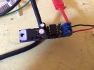
So I got V1.0 prototype of the O2 simulator board in and built one this morning and on a test bench it all works (still don't have a bike).

This is all open source and you are free to do with it what so ever. I plan on selling an early kit in the next week or so with unpopulated board + parts (you will need to solder) and the microcontroller (ATTiny85) firmware you will need to modify yourself (once I have a bike I will provide updated firmware as source). Next version will include surface mount components and a way to externally lean or richen the O2 circuit without having to modify and reflash the firmware.

GitHub: https://github.com/micahpearlman/zero-o2-simulator
OSHPark: https://oshpark.com/shared_projects/4Gi9I2Wu

signal.jpgboard.jpgschematic.jpgfinished-board.jpg
 

mr-fabricator

New Member
Very clever my friend .

Theirs not a lot i cant do myself but ive never realy go to grips with electronics ... the instant u have a unit i can just plug and play count me in ....

Regards lee .
 

micahpearlman

New Member
Very clever my friend .

Theirs not a lot i cant do myself but ive never realy go to grips with electronics ... the instant u have a unit i can just plug and play count me in ....

Regards lee .

I would wait for the Power Commander to come if you want plug n play. It is assumed that it will have a solution.

This is really for me and other tweakers to have fun with. If you don't know what you are doing there is a high probability of ruining your brand new motorcycle.

That being said It's totally possible to derive a plug n play solution with this as a basis. Just really difficult for me to put in that final production quality polish and make it worthwhile.


Sent from my iPhone using Tapatalk
 

mr-fabricator

New Member
I hear u , i have a race dynamics piggy back ecu that im just about to start mapping , wide band installed and a gauge to keep an eye on things . What could possibly go wrong ?? Ha ha

If i can replace the o2 sensor with your box of tricks then thats sweet , if i can set my own afr lower in the rev range to soften the open / closed transition then thats even better

Will be investing in a power commander in the future when we see guud results or i cant go any further with the race dynamics .

regards lee
 
Last edited:

cjwell

Supporting Vendor
Vendor
Country flag
The PCV will have an O2 emulator included, stock O2 will remain inline but you can skew it to desired AFR, like the rest of the emulator applications.
 
Hello.
I'm wondering how PCV can emulate the lambda and/or not use the closed loop.
The idea of generating a ON/OFF signal on O2 sensor input is not valid, because the ECU does not simply check these commutations are present, but it generates a "slightly rich" combustion ... and check to see this at the O2 sensor, then a "slightly poor" combustion and check again at the O2 sensor. The duration and the amout of "slightly" depend of the catalyst used and the overall engine setup.
The goad is not to try to be strictly at stoechiometric level, but to produce exess of oxygen (slightly poor), and excess of HC (slightly rich) in order the catalyst to store some O2, and perform it's job.

Note that the calibration could be quite different depending of the country.
Europe is one one the most restrictive destination, and US calibration (for example) could me more rough (at emission calibration point of view)

A suggestion, if we want (or have to) stay in closed loop, and if we want to be on the rich side, would be to have an electronic that "reads" the O2 sensor level (then, we have to take care of the input schematic to be used as the voltage is very dependant of it), to generate the same voltage to the ECU, but to delay the rising edge. With microcontroller it should not be an issue. Even maybe with simple resistor/capacitor/diode.
It's just an idea. I don't know if it works.

About heating resistance of O2 sensor, this resistor ic PTC, meaning that the resistance is low at low temp (then there is high current, then high power), and high at high temp. To simulate this let's use the high resistor value, then it will not heat.

note : In the last 20 years, I designed automotive EFI ECU at Magnetti Marelli, then Siemens VDO / Continental. And now EFI motorcycle systems, but for a competitor of Bosch.
So I do not know well the Bosch system (but very interested in!)
 

micahpearlman

New Member
Hello.
I'm wondering how PCV can emulate the lambda and/or not use the closed loop.
The idea of generating a ON/OFF signal on O2 sensor input is not valid, because the ECU does not simply check these commutations are present, but it generates a "slightly rich" combustion ... and check to see this at the O2 sensor, then a "slightly poor" combustion and check again at the O2 sensor. The duration and the amout of "slightly" depend of the catalyst used and the overall engine setup.
The goad is not to try to be strictly at stoechiometric level, but to produce exess of oxygen (slightly poor), and excess of HC (slightly rich) in order the catalyst to store some O2, and perform it's job.

Note that the calibration could be quite different depending of the country.
Europe is one one the most restrictive destination, and US calibration (for example) could me more rough (at emission calibration point of view)

A suggestion, if we want (or have to) stay in closed loop, and if we want to be on the rich side, would be to have an electronic that "reads" the O2 sensor level (then, we have to take care of the input schematic to be used as the voltage is very dependant of it), to generate the same voltage to the ECU, but to delay the rising edge. With microcontroller it should not be an issue. Even maybe with simple resistor/capacitor/diode.
It's just an idea. I don't know if it works.

About heating resistance of O2 sensor, this resistor ic PTC, meaning that the resistance is low at low temp (then there is high current, then high power), and high at high temp. To simulate this let's use the high resistor value, then it will not heat.

note : In the last 20 years, I designed automotive EFI ECU at Magnetti Marelli, then Siemens VDO / Continental. And now EFI motorcycle systems, but for a competitor of Bosch.
So I do not know well the Bosch system (but very interested in!)

I think then you would be the expert at designing such a system. My idea was to record the lambda with a scope and play it back, shifted up on down, using a micro controller. What stopped me was the required dyno time to test the system.


Sent from my iPhone using Tapatalk
 
Top